About a year and a half ago, Skye Perry wrote a great article entitled Managing Bandwidth with Fiber Manager™.
In that article, Skye talked about a large client with a very complex telecom network.
That client had recently hired SSP to help manage the network, using a combination of Schneider Electric’s Fiber Manager™ for the physical infrastructure and a series of customizations for the logical network.
Flash forward to today. The design is done, development is well underway, and Skye will be showcasing some of the functionality at Link 2015.
The purpose of this article is to give you a small appetizer before the main course. Reading it will be like watching a Florida Gators football game.
You stay awake only because you know a better game (say, for example, a Big 10 game) is on next. (Letter from the editor: Like most offices around the country, we engage in friendly college rivalry digs whenever possible. Here at SSP Innovations, it’s now spilling over to our blog posts!) That’s where the real excitement is. And that will be Skye at Link. Look for him at the conference in early March.
The focus today will be on Logical Circuit Provisioning. This functionality will allow a provisioning engineer to either provision an entirely new circuit or make changes to an existing circuit.
To start, we open the Logical Circuit Provisioning wizard inside an editing session.
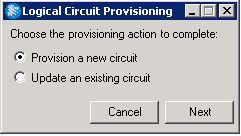
We are first going to provision a new logical circuit, so clicking the Next button brings up the Provision New Logical Circuit window.
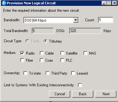
Here you can enter the required bandwidth as well as various other criteria for the proposed circuit.
The bandwidth options are configurable, but for this client, the options are DS0 (64 Kbps), VT (1.544 Mbps), or STS (51.84 Mbps).
There are 24 DS0s per VT and 672 DS0s per STS. Adding a multiplier in the Count field automatically populates the two fields beneath it.
In the example above, we use a bandwidth of DS0 and a count of 5. The total bandwidth will be 5 DS0s; the Kbps will equal 320, which is 5 x 64.
You can also select the Circuit Type (Tributary or Trunk) from this window. A Trunk is defined as a circuit that will reserve the bandwidth but not allocate it within the various systems.
A Tributary both reserves and allocates the bandwidth. Note that a DS0 can only be a Tributary, and the option to select a Trunk will be grayed out if DS0 is selected as the bandwidth.
You can also select three additional values from this window: the mediums which will be included in the circuit; the circuit’s ownership; and how the systems will connect.
If this box is unchecked, paths will be included where the system may connect within the same site but at different devices.
Clicking the Next button brings up the Choose Endpoints wizard. Here, you can select the starting and end points for the new circuit.
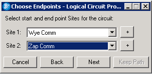
Note that the Keep Path button is grayed out. That is only activated if provisioning an existing circuit with an existing path.
Clicking the Next button brings up the Available Paths form.
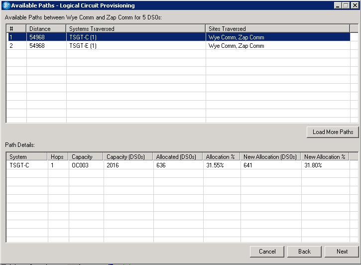
This is where it starts to get exciting! Assuming at least one route between the two sites exist, the window above will appear.
Each row will show the path length per system (in feet), and the systems and sites traversed.
Clicking on a route will shows its details. Above, you can see the system (TSGT-C), the number of hops (how many sites the route traverses within the system), the system’s total capacity in DS0’s, how many of those DS0’s are allocated, and the allocation percentage.
The allocation percentage is calculated by dividing the allocated DS0’s by the capacity. In the example above, 636 / 2016 = 31.55%.
Recall that in our example the new circuit has a bandwidth of 5 DS0’s. The two columns to the far right show the new allocation (636 + 5) and the new allocation percentage (641 / 2016) if this route is selected.
Selecting a route and clicking the Next button brings up the Allocate Circuit window as shown below.
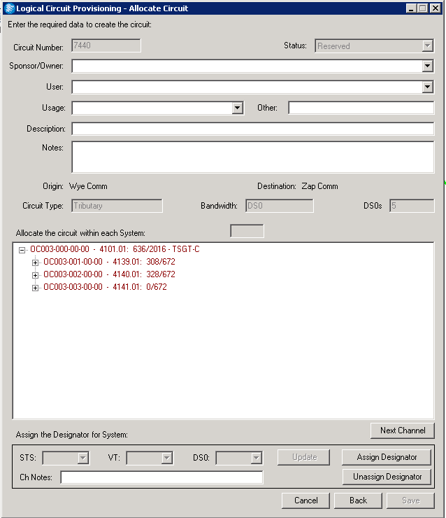
If it was exciting before, it gets even more electrifying here!
First, a new circuit number will be automatically generated. It you selected a circuit type of Tributary on the first screen of the wizard (which we did), the circuit will be in a Reserved status.
As shown in the middle of the screenshot above, the Origin (Wye Comm), Destination (Zap Comm), Circuit Type (Tributary), Bandwidth (DS0), and DS0 Count (5) are displayed. These fields are grayed out and therefore not editable.
From this screen, you can select a Sponsor/Owner, User, and Usage from the dropdowns. This will provide more detail about the new circuit.
You can also enter information in the Description and Notes fields. The main purpose of this screen, however, is to allocate the circuit within the appropriate systems.
Each system is initially shown in red font. Once a user has selected a location in the hierarchy, the color will change to orange.
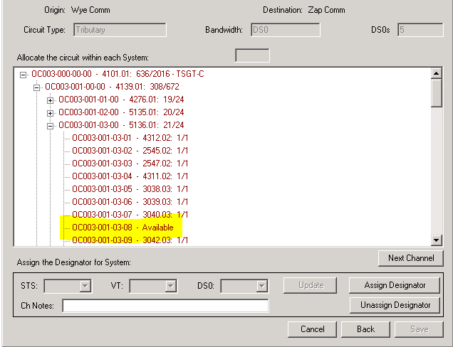
And once the designator has been populated — that is, once a user clicks the Assign Designator button — the color will change to green. In the example below, we have expanded the hierarchy and selected an available location:
A couple of things to note once we click the Assign Designator button. First, note that the font color changes from red to green (it’s like Christmas!) and the circuit has been placed in the spot selected.
Second, note that the “designators remaining to assign on TSGT-C” changes to 4.
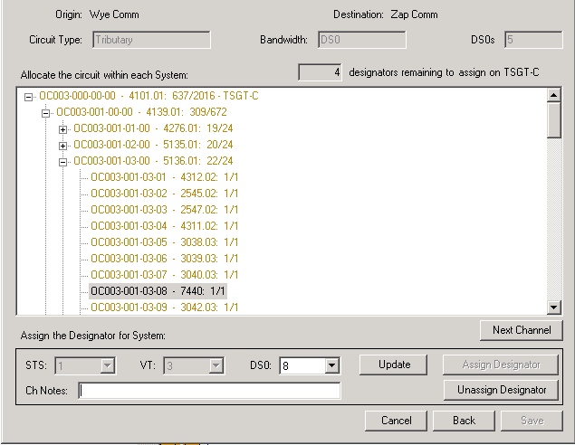
At this point, you can unassign a desginator by clicking on the Unassign Designator button.
In the example above, that would return OC003-001-03-08 to a status of Available and the designator count from 4 to 5.
You could also move the circuit to a different part of the hierarchy by selecting a different DS0 from the DS0 dropdown.
If you select a DS0 that is unavailable, however — for example, selecting OC003-001-03-07 in the example above — you will get an error message similar to this one:
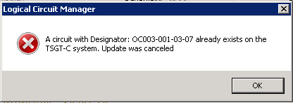
But … if you selected OC-003-001-19 instead, this would move the circuit from -08 to -19. -08 would move to a status of Availabe and -19 would be populated with the new circuit number.
In the example below, the designator count would remain at 4 because you are just moving the cicuit from one available spot to another available spot in the hierarchy.

If, however, you clicked on an available spot in the hierarchy and clicked the Assign Designator button instead of the Update button, the Circuit would now show up in both locations (-08 and -19), and the Designator could would decrease from 4 to 3.
Once all designators are assigned in the hierarchy, the Assign Designator button is deactivated and the Save button beomes activated. Once you click the Save button, the following message will appear:
Success! Clicking the Next Channel button at this point will show where in the hierarchy the circuit resides. Each click of the Next Channel button will jump to the next location for that circuit.
So that was provisioning a new circuit. Check back a little later for Part 2 where we update an existing circuit.
Did we lose you at any point in the article? Need a better explanation? Let us know in the comments below!

Anonymous says:
Good Article, Matt. I like the use of the screen shots to help explain the technical concepts. Looking forward to your next article to learn more about how the system works.