Those that have implemented Schneider Electric’s Fiber Manager™ or have worked with it at all understand that the product focuses on managing the physical infrastructure of your telecom network including fiber optic, microwave, copper, and various other communication mediums. Fiber Manager™ does a great job of geographically and logically tracking the physical telecom facilities as well as the connectivity between those facilities. More advanced users will fully utilize the product by tracking end-to-end circuits which define physical connectivity between facilities down to the lowest physical level – the fiber strand, the microwave frequency, or if you get a little creative, the lambda level when implementing WDM.
If you noted that I used the word “physical” more than a few times in the above paragraph, it’s not just because I am lacking in the use of creative words. Fiber Manager™ is all about the physical infrastructure. This solves many problems within our customers’ organizations, whether they are utilities or in the private sector.
But some of the larger customers have long been interested in managing the logical network in addition to the physical infrastructure. And this means managing bandwidth allocation to the various users, systems, services, or customers whose traffic traverses your physical facilities.
Schneider is well aware of this requirement and has been looking for opportunities to explore how this logical network management could be achieved. SSP recently signed up a custom Fiber Manager™ implementation with one of these larger customers and we’ve teamed up with the Fiber Manager™ Product Owner, Ryan Potts, and our very own telecom subject matter expert, Bob Fasulkey, to take on the challenge.
We’re currently in the early stages of design and will certainly keep writing about the solution as it comes to fruition – but I wanted to get this article out on the front end to solicit input from any other Fiber Manager™ customers.
Our current client manages a large and complex telecom network made up of fiber, microwave, copper, power line carrier (PLC), and even some satellite communications. They are primarily SONET-based and have several interlinking SONET rings with current bandwidth capacity up to an OC-48 (2.488 Gb/s). In the future, they may also manage higher levels of bandwidth – up to an OC-192 (9.953 Gb/s) level.
On the flip side, they need to be able to allocate bandwidth to specific services all the way down at the DS0 level (64 Kb/s). To put it in perspective, there are 32,256 individual DS0’s in the above-mentioned OC-48.
In other words, this is no simple challenge.
We’ll start by using Fiber Manager™ to manage their physical infrastructure and will establish physical circuits (named paths) within the network. Their network contains large numbers of optical devices (switches, channel banks, etc) at many of their patch locations, which means that there is not physical connectivity through the patch locations.
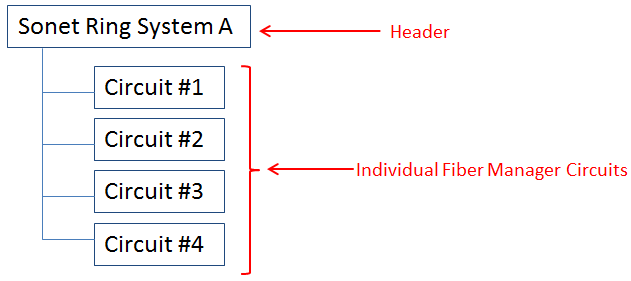
The data flows into these optical devices and can be routed in any combination of different directions. Our first custom goal will be to join multiple physical circuits together to establish the concept of the SONET rings or “systems”.
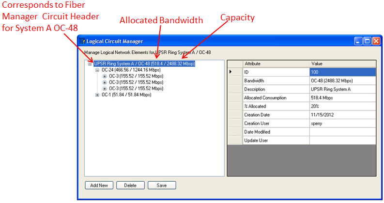
We then plan to establish a master logical circuit related to each system that defines the total capacity of the circuit – i.e. the OC-48 we discussed above.
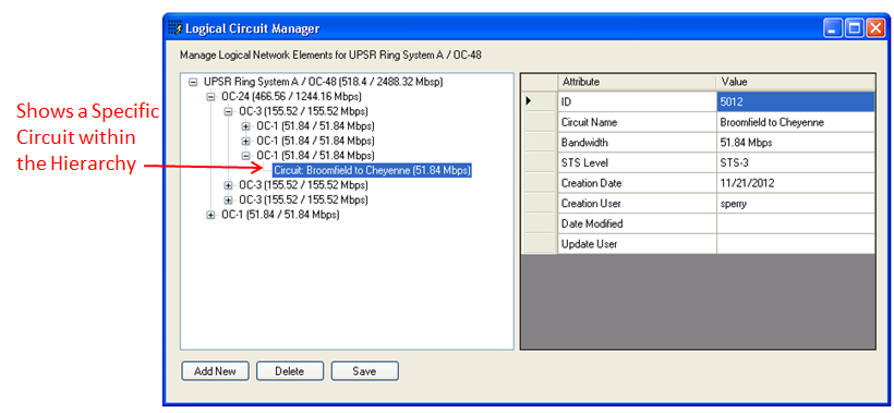
Next, we will be working to establish custom software to allow users to manage the hierarchy of bandwidth allocation within each of the systems. Each system (OC-48) can be broken down into various bandwidth levels such as OC-3’s, OC-1’s, different STS levels within each (each STS level carries the equivalent of a DS-1/T1).
We can provide additional intelligence by tracking the capacity and the allocated usage at each of the hierarchical levels. Users can delve down into the hierarchy until they can see the individual circuits that are dedicated to the usage of a specific service (SCADA, telephone, etc).
With this logical bandwidth hierarchy in place we, can do some pretty cool stuff to create new circuits.
We plan on creating a custom two-point trace that can traverse across physical Fiber Manager™ circuits and even across systems (across multiple SONET rings). This will allow a user to choose any two patch locations in the entire network and find a path between them.
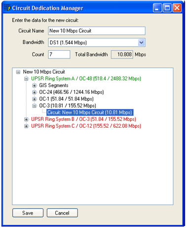
The software can then determine which systems were encountered along the path and will allow the user to allocate a new logical circuit within and between those systems:
This dialog will allow the user to input a circuit id/name, choose the amount of bandwidth that is needed and then allocate the circuit within each system that was identified by the custom two point trace.
As the circuit is allocated within each system, we plan on changing the color of the system from red to green and will increase the allocated bandwidth for each system based on the circuit’s bandwidth:
As mentioned above, we are just entering the formal design phase and will be doing a lot more prototyping around these ideas. If any of you have any thoughts on the topic we’d love to hear from you either via the comments section or via our contact page.
I’ll write another article once we get further along in the process!


What do you think?