Regardless of which commodity is being distributed, anyone involved in mapping, engineering design, data management or field data collection at any utility is familiar (or soon to be familiar) with the concept of a geometric network.
For those of you who are new to GIS for utilities, a geometric network is a collection of interconnected points (junctions) and lines (edges) that are given additional properties and configuration settings that allow us to model the behavior of real-world electrical, natural gas, water, sewer or fiber optic / telecommunications distribution systems.
Geometric networks are the best method for modeling these types of systems, and they allow end users to perform a myriad of analyses that can improve the operational efficiency, safety and regulatory compliance of these utilities. The geometric network model was originally developed years ago by Esri, and has since been refined and given broader business intelligence by Esri, Schneider Electric (formerly Miner and Miner), SSP Innovations and other organizations.

Whether your utility is pursuing the implementation of a new ArcGIS / ArcFM™ system, maintaining an existing one, or designing new construction projects to keep up with ever-growing customer demand, you will be faced with data problems that prevent your GIS from accurately modeling the connectivity of your distribution facilities.
This article uses a recent implementation of ArcGIS 10.2.1, ArcFM™ 10.2.1, and Schneider Electric’s Feeder Manager II, as examples of some of the common data problems that are encountered with geometric networks. Although the examples are all based on an electric utility, the problems described and the methods used to find and solve the problems are the same as what would be found and used with implementations for other utilities.
When you and your organization encounter problems like these, there is really one simple thing you need to remember. Do like Johnny Cash, and Walk the Line.
Some of the most common of these data problems are known as loops, multi-feeds, and islands.
Loops are situations where a feeder loops back and connects to itself. Perhaps you might think of these and remind yourself of what they are by by comparing it to one of my favorites that Johnny ever sang (which was actually written by June Carter), Ring of Fire. When a loop condition is present, the Loop field is populated with a “Yes”.
Multi-feeds are situations where more than one feeder is interconnected, causing Feeder Manager II’s FeederIDs field to show more than one feeder. You’ll have to go deeper into Johnny’s discography for a song to remind you of this one. He has a lot of songs about food, but my personal favorite is the title track from his 1975 album, Look at Them Beans.
When a multi-feed condition is present, the Feeder IDs field will be populated with more than one feeder ID, and the Number of Feeders field will have a number greater than one.

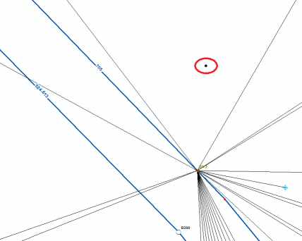
The image above shows an example where both the Ring of Fire and the Look at Them Beans conditions exist.
Yet another data problem that is commonly encountered is what is known as an “island”. Islands are portions of the geometric network that are not connected to the rest of the network.
Islands can be as simple as a service location that isn’t connected to a transformer by a secondary (or service) line, or they can be entire neighborhoods that are isolated from the rest of the geometric network because of a gap in the feeder line that feeds that neighborhood. Islands are identified when you build a geometric network in a table named %NetworkName%_BuildErr.
It would be a big mistake if we weren’t to coin this condition Rock Island Line, which Johnny recorded several times and was the title track to his 1970 album, named – you guessed it – Rock Island Line.
There are still other ways that a geometric network can misrepresent your utility’s distribution system. Many of the data problems stem from quirks in the source data that was used when building the first implementation of the network. Others are produced as a side effect of some of the functions that are used to build the network itself. Still others can be created by user errors when manually editing an existing geometric network.
Regardless of the efficacy of the problem, there is one tried-and-true method for finding, troubleshooting and fixing all of these different issues. Within our very small community of utility GIS geeks, it is colloquially known as “walking the line”.
Please don’t close your browser right now! I am not suggesting that you go buy a new pair of running shoes and hit the streets. In the paragraphs that follow, I’ll give you the steps you can perform from the comfort of your office chair.
-
View your data in ArcMap with an MXD or an ArcFM™ Stored Display that shows all of the features in the geometric network. If you have a field that shows the legacy feeder ID in the attributes of the polyline feature classes that participate in the geometric network, it is a good idea to label your lines with those values. You will want to these legacy values to the FeederIDs field that is populated by Feeder Manager II based on the connectivity that is in your network.

-
Make a list of the feeders that participate in multi-feeds. Multi-feeds will cause you the most problems when analyzing your geometric network with tracing and other tools, and until the multi-feeds are cleaned up there really isn’t much point in taking time to fix loops or islands.
You might choose to fix loops and islands on the feeders as you walk them, or as a seperate effort.
- Create a new version or session, switch to it, and start editing.
- For each feeder in your list of multi-feeds, you should go to the circuit breaker at the substation where that feeder starts. In Feeder Manager II, you can use the Find Feeder tool to select a feeder, zoom to the extent of the feeder, or zoom to the source of the feeder.Make sure all of your features that participate in the geometric network are visible at the zoom reange you will be working in, including the network junctions feature class.

-
Now, walk the line. Pan downstream of the circuit breaker and make sure to follow every branch of the primary conductors as you investigate connectivity of the feeder. Make sure to perform your investigation until you find the connection (or all of the connections) where the feeder you are investigating is interconnected with other feeders.
- When you look for the interconnections, be on the lookout for the following conditions: tie-in switches that should be set to “normally open” but are not, places where features belonging to different feeders were mistakenly connected by a user, or places where primary or secondary conductors belonging to your feeder cross conductors that belong to other feeders and the crossing caused a connection to be created when the geometric network was built.
- Tie-in switches that have values set to “normally closed” should be opened. Opening these switches (on all phases) will eliminate the multi-feed situation coming from the feeder that is tied in.
- Use the ArcFM™ (or ArcGIS, if you don’t have ArcFM™) Disconnect tool to disconnect the other feeder anywhere the two feeders are mistakenly connected to one another. Use other editing tools to edit the geometry so that the two lines are not mistakenly connected.
- Test places where you find lines from your feeder crossing conductors from other feeders. The easiest way to determine if there is an unintentional connection there is to double-click on your feeder’s line, which will start the Edit Vertices toolbar and will show you points displayed at every vertex on the line. Grab the vertex that occurs at the location where the line-crossing occurs and move it slightly. If all of the line ends from both feeders nove with the vertex you are moving, then the feeders are interconnected here. Escape out of the move vertex operation, or roll it back.
- Similarly, use the ArcFM™ (or ArcGIS, if you don’t have ArcFM™) Disconnect tool to disconnect the other feeder from where the two feeders are mistakenly connected to one another. Next, delete the vertices that are on both of the crossing lines at the location where they cross.
- Save your edits. Feeder Manager II should update with all of these edits.If the place where you were editing was the only place where there was interconnectivity between your feeder and the other feeder that you have just disconnected, the other feeder’s ID should drop out of the FeederIDs field for your feeder, and the value in Number of Feeders field should decrease by 1.
If there is only one feeder shown in the FeederIDs field, and the Number of Feeders field equals 1, then you have isolated your feeder from the other feeders in your system, and you’re finished with this feeder.
If these fields still show you that interconnections are present. you have more work to do.
- You can periodically verify the progress you have made while walking the line by disconnecting the portion of your feeder that you have already walked from the downstream portion that you haven’t yet investigated.Do this by disconnecting the upstream portion of your feeder from the downstream portion. Double-click the last line segment of the upstream portion, and then drag the line end off of the point that you just disconnected your feeder from. This will create a gap in the feeder you are currently walking.

- Next, check the FeederIDs field and the Number of Feeders field on your feeder upstream of the diconnection gap you created. You should see only one feeder ID in the FeederIDs field, and the Number of Feeders field should show 1 as the value.
- You can also perform a distribution trace on the portion of the feeder that is upstream of the diconnection gap you created. You should see only the correct results from this trace, going downstream from the circuit breaker to the disconnected gap that you created.These two tests should assure you that the portion of the feeder that you have already walked is now in good shape, but you’re not finished yet…
- Fix the gap you created, and re-connect the top portion of your feeder to the bottom portion.
- Continue walking the feeder downstream, and repeat steps 6 through 14 until your feeder is isolated from the rest of your network. Your trace results should reflect what you know about the feeder now, and your FeederIDs field and your Number of Feeders field should also be correct.
- Now you can move on to the other feeders in your list.
Once all of your feeders are all isolated, trace results accross your system will be predictable, be correct and reflect what you know about your system.

What do you think?