
This month I wanted to turn my attention back to another Telvent Feeder Manager topic that has generated a lot of interest over the last few years. More and more electric utilities are building integrations and/or interfaces to outage management systems (OMS), distribution planning systems (DPS), and engineering analysis systems (EA). The expansion of these system touch points has placed an ever-increasing importance on the integrity of your electric data within the GIS. A simple connectivity issue or incorrect attribute in the GIS can have ramifications far beyond the mistake itself because those GIS data properties affect the modeled flow of electricity, the extents of the individual circuits, and even the energized phases.
If this data is passed to an OMS, DPS, or EA it could significantly change the results generated within those applications which then affects field operations, design planning, and managerial decision making. This article will focus on some effective ways to ensure that the data entered into GIS meets the more stringent electrical requirements of these important applications within your organization
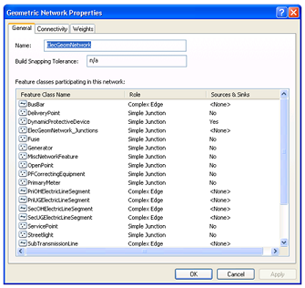 At the root of the issue is the electric connectivity which is typically managed by the Esri geometric network. The geometric network defines a list of the point and line features that will be snapped together to define the electric network.
This list will include everything from your substation circuit breakers, your primary, secondary, and service conductor, and all of the devices that might be encountered along the way.
Any utility using Telvent Feeder Manager has an electric geometric network defined, as this is the foundation that allows Feeder Manager to trace, analyze, establish, and maintain your distribution (and often-times transmission) feeders/circuits.
Many utilities have then taken the next step of defining their electric network connectivity rules. This is performed within the core Esri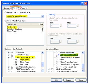 configuration tools which allow you to specify connectivity rules that govern exactly which feature classes can connect to other feature classes at the subtype level. It further allows you to configure the allowable connectivity counts.
For example, you would typically configure a rule that would allow a single phase OH secondary conductor to connect to a single phase OH primary conductor via a single phase OH transformer bank.
This rule will flag an error/issue if a single phase secondary connects to a single phase primary without a transformer or if it connects via any other electric device other than a transformer.
The connectivity counts (cardinality) for a transformer bank can then be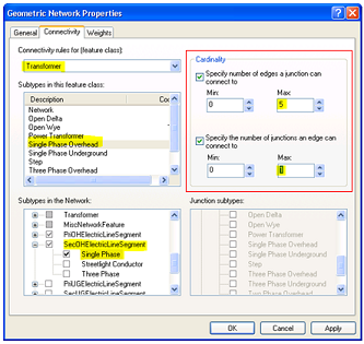 defined. In this example we are configuring a single phase OH transformer’s connectivity to a single phase OH secondary line. We have indicated that a single transformer bank can connect to up to five secondary records and that a secondary can only be connected to one transformer bank.
We have set the minimum cardinality to zero in both cases indicating that these are not mandatory connections (this allows us to make connections to other secondary subtypes like a Streetlight Conductor).
This rule would then flag an error/issue if we had a single phase secondary line that was connected to two transformers on either end which is obviously an invalid case.
The connectivity rule examples shown above are nothing new to Esri but we have found a number of electric utilities who are not taking advantage of this out-of-the-box configuration. Telvent has further allowed utilities to utilize this configuration via their ArcFM™ QAQC Validation tools. When you run the Telvent ArcMap QAQC routines on either a selected set of data or on all 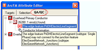 of the edits in your version, it will validate the data against the geometric network connectivity rules you have configured in your geodatabase.
Any errors or issues will be reported on the ArcFM™ QA/QC tab of the ArcFM™ Attribute Editor to allow the user to easily find and correct any problems within the data. Running this validation before electric edits have been posted can greatly increase the integrity of your connected electric data before it is passed to OMS, DPS, or EA.
But what if we wanted to take the data integrity to a whole new level? In a past article we explored how you can interrogate the electric trace weight and feeder info fields on your feeder manager features. We can use this information along with a few standard feeder manager attributes to create a custom ArcFM™ QAQC Validation rule that is specific to your feeder manager edits. This custom rule can be configured right in-line with the out-of-the-box Telvent QAQC Validation rules which allows it to seamlessly QAQC all of your electric edits in new and valuable ways. We have worked to define the most common electric rules to include in this type of validation:
- Null Feeder ID: This is the most straight forward check which will simply validate that the Feeder ID / Circuit Number is populated on any electric data that you have created or edited. The Feeder ID is automatically set by Feeder Manager when you have connected your data into a valid, energized circuit.
- Valid Feeder Info: This check will ensure that a valid feeder info value exists on the edited features. The feeder info attribute is a bitgate that drives a fair bit of functionality within Feeder Manager and certainly impacts the circuits that are defined within the software.
- Dropped Phases: The next check will compare the phase value on the edited features to energized phases as recorded by Feeder Manager within the feeder info attribute. As feeder manager traces out your electric feeders, it records the energized phases via certain bits within the feeder info bitgate. This specific check will allow the user to review any location where the energized phases do not match the phase set on the feature. For example if a three phase primary OH line has its phase attribute set to ABC but only phase A is energized, this rule will flag that as an error condition for further review.
- Loop Condition: This validation will check to see if the edited features are marked as existing within a loop condition. If feeder manager determines that a feature is being energized from two differing directions it will flag this condition into a bit within the feeder info bitgate. This might indicate that the user missed adding an open point or possibly connected the features incorrectly.
- Multifeed Condition: This validation will check to see if the edited features are being fed by more than one circuit source. Similar to the loop condition, feeder manager will flag this out within a feeder info bit. This condition could cause many problems both within the GIS and within any of the other systems that depend on this data. It would likely indicate that a switch was not closed correctly or that connectivity was incorrectly established between two circuits.
- Island Condition: This validation will check to see if the edited features are marked as an island. Once again, feeder manager captures this data within a feeder info bit. The island condition is typically flagged on disconnected data when the “Trace ALL Feeders” routine is executed. This validation just double checks that if this data is edited by a user that they didn’t miss connecting it into a valid circuit.
By building these checks into an ArcFM™ QAQC Validation rule we make them accessible to the entire organization through the existing Telvent framework. The ArcFM™ QAQC tools will then catch all of these error conditions before the data is posted to the default version. As mentioned above this will occur when the QAQC routines are executed manually within ArcMap and will also apply if you configure your BRP (Batch Reconcile & Post) or Telvent Geodatabase Manager™ applications to automatically run the QAQC validation rules before any automated posting occurs.
In either case, if the data passes all of these validation rules then you have a much higher chance of ensuring the overall integrity of your electric network both within the GIS AND when you pass this data to an OMS, DPS, or EA. By automating this validation process you will enable your GIS department to process more electric edits in an efficient manner by allowing them to catch any costly mistakes before they impact the larger organization. And all without modifying the way they work today (assuming you already use the ArcFM™ QAQC routines… which we recommend to every utility).
I hope this article has sparked some thoughts about how you can increase the integrity of your electric data. This article mentioned OMS, DPS, and EA but this topic garners even more interest when you start talking about preparing your data for smart grid. Taking these steps now will ensure your data is ready for the technical challenges of today and for many years to come.

What do you think?