
As summarized in a previously published case study, Colorado Department of Transportation (CDOT) recently expanded their GIS capabilities to include multiplexing. CDOT recently approached SSP with another fiber requirement to include traffic light management.
CDOT maintains numerous traffic signals and many of them are coordinated to enhance traffic speeds. To coordinate, the traffic signals are connected together and managed via common fiber strands (Figure 1).

As shown in Figure 2, this equipment has four optical ports as follows:
- Port 1: Secondary Transmit (TxB)
- Port 2: Primary Receive (RxA)
- Port 3: Primary Transmit (TxA)
- Port 4: Secondary Receive (RxB)

The traditional Fiber Manager™ model considers devices to be the “end of the line”. In other words, tracing the signal path would terminate when encountering a device. When using Fiber Manager’s™ Connection Manager, one would only connect the appropriate fiber strand(s) to the device’s port(s).
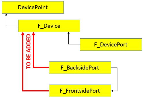
As shown in Figure 3 and using the standard model, the end device point feature class (DevicePoint) has one related child object (F_Device). The F_Device object itself has one child object (F_DevicePort).

It is actually quite simple to modify the model to achieve the required functionality of the signal device. The required tables and fields are already present. Two additional Esri relationships (Figure 4) are required between the following objects:
- F_Device and F_BacksidePort
- F_Device and F_FrontsidePort
There are also some ArcFM™ configuration properties that must be modified as follows.
- Add the FIBERMULTICONTAINER model name to the F_Device Object.
- Add the ArcFM™ Update Fiber Parent Field AU to the two new relationships.
Because the F_Device table now has multiple child objects, the field FIBERCHILDCLASSMODELNAME default value can no longer be set and should be removed. The default value will actually now come from the child objects and will be established from an ArcFM™ Favorite(s). Traffic signal favorites should be constructed with the FIBERPARENTCLASSMODELNAME field for F_BacksidePort and F_FrontsidePort tables set to ENDDEVICE.
It should be noted that if any existing favorites were previously constructed using the traditional device model, the FIBERPARENTCLASSMODELNAME field for F_DevicePort should also be set to ENDDEVICE.
Once constructed, one is able to digitize and connect using Connection Manager as shown in (Figure 5). The internal connections of the device are now modeled in the same fashion as connectors on the front side of a patch panel.

If digitized and connected properly (and it can be confusing), the user will be able to trace an individual traffic light circuit. One difference between the traffic light circuit and a “normal” fiber circuit is the physical beam of light is actually stopped and regenerated at each signal. As a result, although Fiber Manager’s™ trace report is extremely valuable for route determination, the total accumulative attenuation loss isn’t completely applicable.
SSP would like to express appreciation to the staff of CDOT (Cameron Emick, Michael “Milo” Lopez, and Brandon Carrick) for contributing to this blog post and providing some of the images.


What do you think?