While writing this fiber blog, I had to think back almost 15 years to when I was an analyst at a utility and given the task of mapping out our fiber infrastructure. At the time, I had little knowledge of fiber optics other than being able to identify a cable and even though we had a new software program, Fiber Manager, to manage these assets, it was still in beta and had little to no documentation. Still, I had to come up with a way to understand equipment I had never even seen before. It was overwhelming to say the least!
I cobbled together as many questions as I could think of and went to our resident fiber expert, Manny, to figure out this seemingly impossible task. With Manny’s help, we embarked on several field trips across our service area so that I could get a look at the actual equipment. This was invaluable in helping me understanding the purpose of each piece of equipment and how it should be modeled in the new program. The one exception to this was the patch panel and their internals.
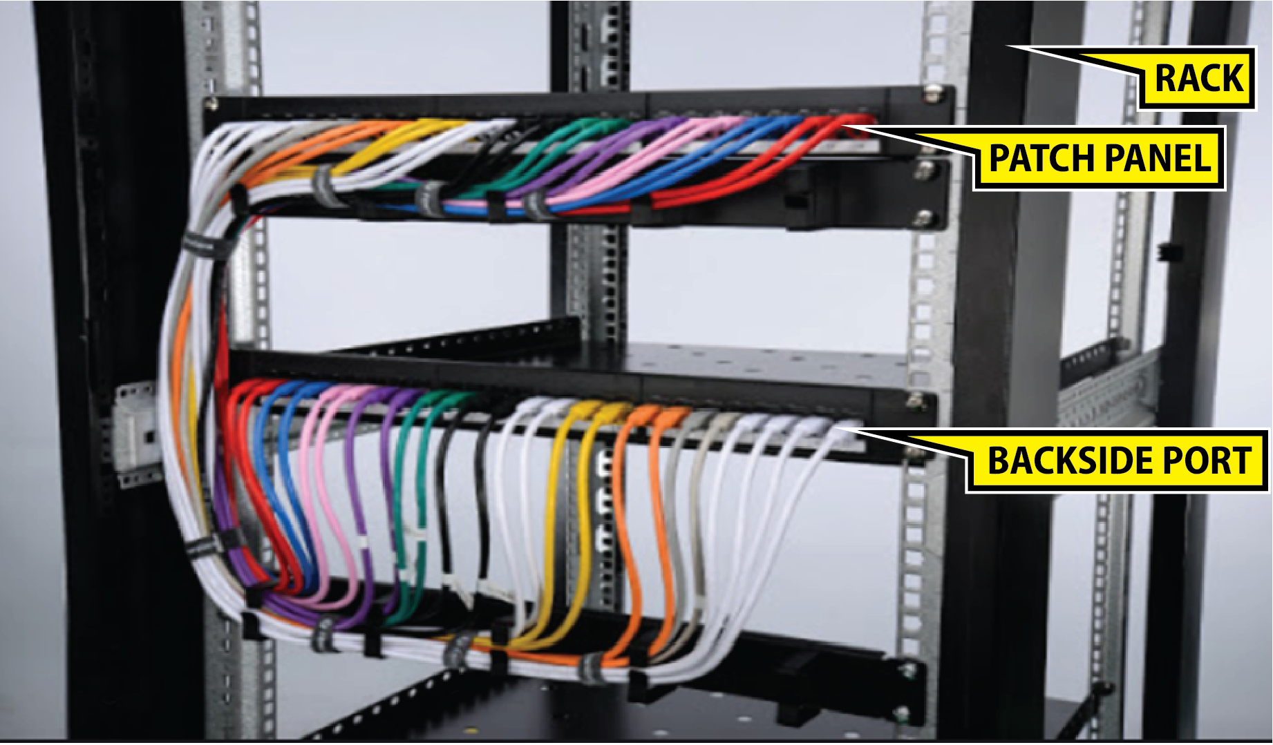
Grasping how the components of a patch panel, such as racks, panels, cards, and ports, all fit together was a lot harder to grasp. Since I knew that Fiber Manager was highly dependent on relationships, I decided that creating my first patch panel favorite would be the best way to understand how the software managed all of the device’s components. Trust me when I tell you that you will want to spend the time to create these favorites up front rather than trying to build them on the fly as you’re editing data.
First, Manny explained how the components of the patch panel work in the real world. Patch panels were mounted in simple metal structures called racks. The patch panel itself was a hardware encasement that was made up of a number of cards. Each card was then made up of a number of ports oriented in a variety of different configurations with each port having a both a frontside and a backside.
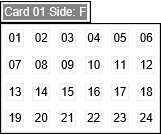
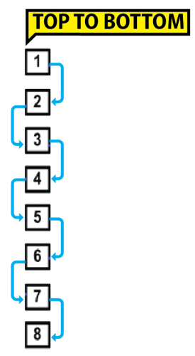
Next, I had to decide how to convert the pictures for the patch panels I had taken in the field into a single Fiber Manager favorite. Since I knew that the patch panel cards were going to be the building block for all my patch panels and therefore patch panel locations, I wanted to build a library of different cards. Using the pictures as a guide, , I was able to determine how many cards there were in the panel and most importantly how those cards were arranged; the arrangement of the cards, whether horizontal or vertical, is a critical step in setting up the favorite correctly Furthermore, the pictures also showed how many ports there were on each card and how those ports were arranged. Knowing that the cards were going to be a building block for all my patch panel locations I wanted to build a library of different card configurations. Below is an example of a 4×6 card I created. In the example below you’ll notice that the layout of the card, which is indicated by port number, is arranged from left to right and then top to bottom. This is always going to be the standard reading/interpretation direction when dealing with the patch panel cards.

Based on my experience, these are some of the most critical/common pieces of information was needed to capture when creating patch panel card favorites:
Name – A name or number that the client can assign to a card within a patch panel. This may vary from the CardNumber used to determine the position of the ports.
Position – The position where the card is on the panel.
Number of Port Rows -Specifies the number of rows of patch panel cards arranged within the patch panel. In the example above, there are 4 rows.
Number of Port Columns – Specifies the number of columns of patch panel cards arranged within the patch panel. In the example above, there are 6 columns.
Default Port Width – The width of the port in the patch panel report – the default is 1.
Default Port Height – The height of the port in the patch panel report – the default is 1.
Appears on Rack Sides – Which side of the patch panel connections can be made from. To create connections on both sides of a patch panel, use ‘FB’ (Front/Back).
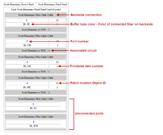
Once I created the framework for the card, I needed to save the card and expand the card to see its child relationships. By right clicking one of the child relationships I added the related objects. For the example below I had to create related objects for the backside and frontside ports. That means creating 24 of each of these. In an effort to save time I created one of each with the information populated below and then copied and pasted the additional related objects making sure to populate the information for each record.
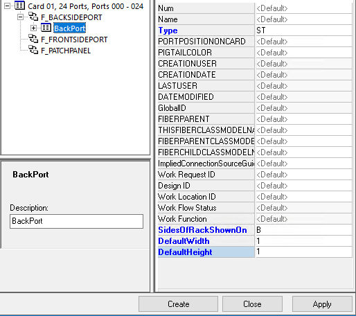
After completing this step, it was only a matter of updating the number and name of the related objects to match the ports in the card. Having built out several variations of these cards I was able to easily create the most common patch panels in our system simply by dragging and dropping the cards into the new patch panel favorite. This enabled our technicians to easily map out our fiber infrastructure without having to spend extra time building out complex patch panels.
Below are a few links to previous SSP blog posts that you should find helpful in mapping out your own Fiber networks.
https://sspinnovations.com/blog/fiber-manager-device-modeling/
https://sspinnovations.com/blog/go-ahead-make-my-fiber-manager-favorite/
https://sspinnovations.com/blog/fiber-manager-cable-favorite-tool-everybody-wang-chung-tonight/


What do you think?