A year ago, SSP wrote a blog on Esri’s Utility Network Management extension and its ability to trace gas features. That article gave an initial view into the core tracing capabilities available to gas organizations being provided in the ArcGIS platform with the new Utility Network Management Extension. With the upcoming release of ArcGIS Enterprise 10.7 and the recent release of ArcGIS Pro 2.3, the core tracing capabilities are being enhanced to include an isolation option. This addition of an “isolation” option to the Trace geoprocessing tool provides a true gas isolation tracing capability. This new capability makes it easier than ever to leverage your ArcGIS System for gas emergency responses.
Why was this option added to the utility network? To answer this question, we reached out to the “gas guy” at Esri, Tom DeWitte. Tom DeWitte is the Technical Lead for the Natural Gas Industry at Esri. Tom had the following to say about why this new capability was added to the utility network. “With the Geometric Network and ArcMap, we were seeing a strong adoption of the Gas Utility Tracing toolbar which we offered as a free add-on for ArcMap. For the Utility Network Management extension, we wanted to fold this popular add-in into the core product. Our goal was to make it easier for gas organizations to deploy this critical tracing capability.” (The ArcMap Gas utility tracing add-in can be downloaded from here: http://solutions.arcgis.com/utilities/gas/help/as-built-editing/ )
ISOLATION TRACE FOR GAS
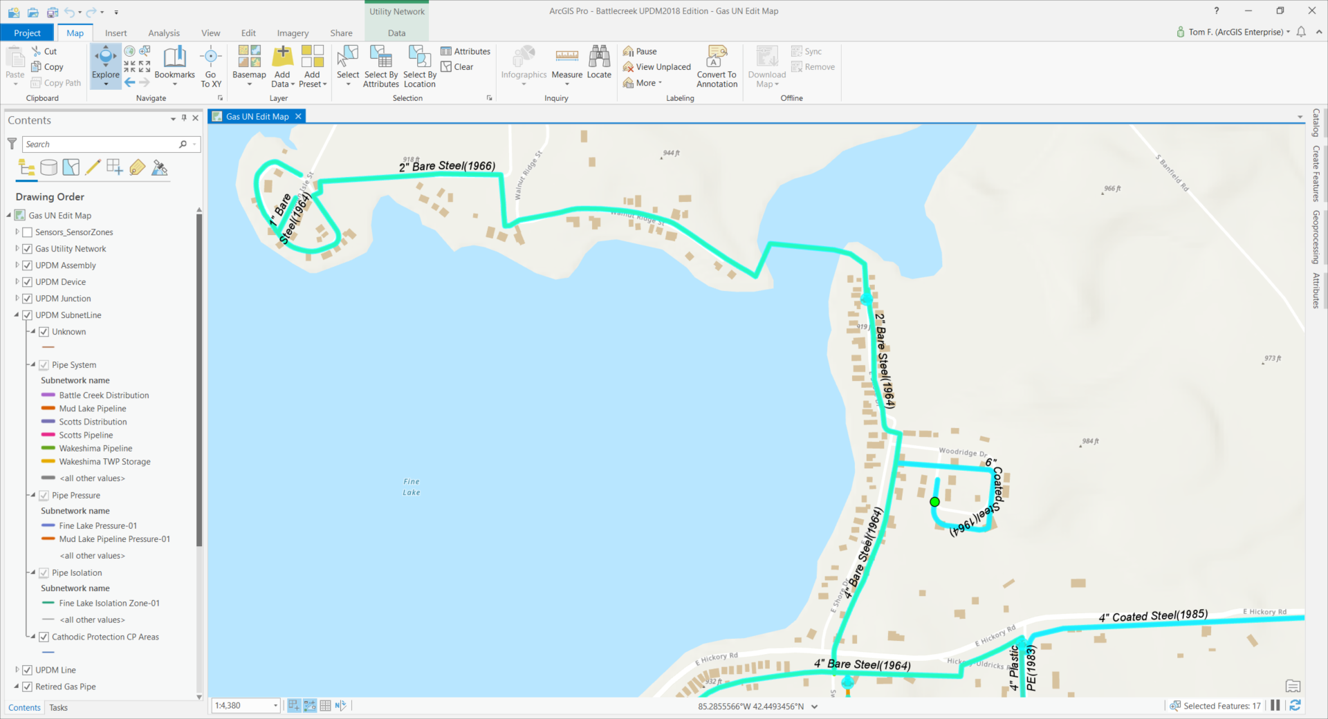
So, what makes isolation tracing for gas so unique? Understanding why a gas isolation trace is such a unique type of trace requires a quick review of gas distribution pipe systems. In general, a single pressure zone within a gas distribution system is fed gas from multiple locations to maintain a more consistent pressure across the pressure zone. If a pipe system failure occurs within the pressure zone, only a subset of the pressure zone customers need to be isolated and the remaining portion of the pressure zone customers can continue to operate because they are continuing to be fed gas from the additional regulator stations (ie. sources). If this were always true, then a simple connected trace to identify isolating valves or plastic pinch points would be all that is needed to identify the impacted customers. Unfortunately, this is not always true. There are portions of pipe systems often called “dead ends” which are fed gas from a single regulator station. Because of this, the isolation trace needs to determine whether the pipe system on the non-isolated side of the isolating devices is being fed gas from another source. The screen shot below provides an example of this exact scenario
Figure 1

The customers on the north side of Fine Lake are provided gas from a single source (ie. regulator station). An isolating valve exists between the customers on the north shore of the lake and the regulator station providing them with gas. Should a system failure occur at a location between that isolating valve and the regulator station, such as is marked on figure 1, the customers on the north shore need to be included in the results of the isolation trace because they too will be without gas. The isolation trace needs to understand that the isolating valve for the north shore customers should be ignored, and the trace should continue to select features on the downstream side of the isolating valve. Figure 2 shows the result of the isolation trace, which included the north shore pipe system as part of the trace selection set.
Figure 2

This understanding of single-fed pipe sections vs multi-fed pipe systems is what makes the gas isolation trace unique.
CONFIGURING THE ISOLATION TRACE FOR GAS
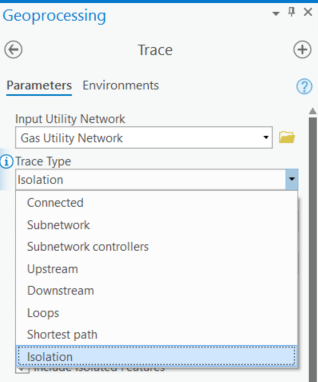
Configuring the geoprocessing trace tool to perform the gas isolation trace, is very straight forward. The first step is to set the trace tool Trace Type to the new option called “isolation”.
Figure 3

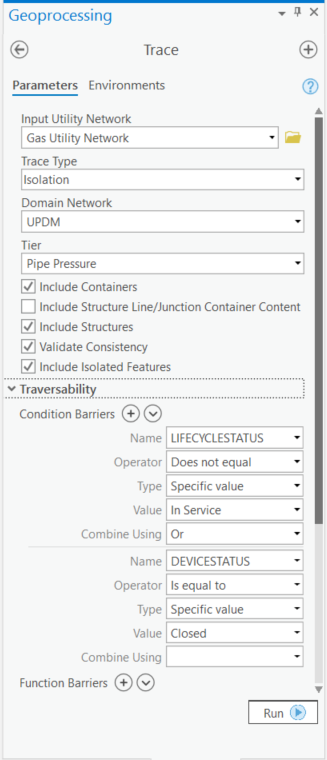
Second step is to determine which assets in the utility network are to be included in the trace. This is the check boxes listed in figure 4, under the Tier setting. There is a new option to the list of check boxes added specifically for isolation traces. This new option is called: Include Isolated Features. I checked the box for this option because I want my isolating valves to be included on the trace result selection set.
Third step is to specify in the Traversability section what characteristics of the pipe system assets will stop the trace. In my example I have set the trace to stop at any pipe system assets which is not “In Service”, and to stop at any device which has its DEVICESTATUS set to close. Examples of this are assets whose LIFECYCLESTATUS has been set to “proposed” and valves whose DEVICESTATUS has been set to “close”.
Figure 4

When the trace tool is run, it will select the pipe assets of the pipe system which will be isolated from their source of gas when the selected isolating valves are closed, or the specified barriers to identify plastic squeeze off locations are clamped closed.
If your ArcGIS-based pipe system includes each customer’s meter, then you now have the list of customers impacted by the system failure. A simple Append tool can upload the impacted customers to a feature layer for use by Mobile apps such as Workforce and Collector to manage the gas relight portion of the gas outage event.
With the release of ArcGIS Enterprise 10.7 and ArcGIS Pro 2.3 Esri has further enhanced its core set of capabilities for meeting the analytical needs of gas organizations. The addition of an isolation option to the Trace geoprocessing tool further simplifies the ability for gas organizations to easily and accurately define assets and customers impacted during a gas outage event.


What do you think?